Índice
- Princípio estrutural e de funcionamento das rodas motrizes e rodas dentadas de escavadeiras
- Análise dos padrões de desgaste comuns e das causas de falhas
- Como selecionar cientificamente rodas motrizes e engrenagens
- Etapas e precauções para a substituição da roda motriz e da roda dentada
- Por que escolher a GFM para a fabricação de rodas motrizes e rodas dentadas?
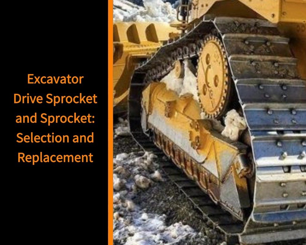
Princípio estrutural e de funcionamento das rodas motrizes e rodas dentadas de escavadeiras
A roda motriz e a roda dentada são um dos componentes de transmissão de potência mais críticos no sistema de material rodante de uma escavadeira de esteiras. Sua função é transmitir o torque do motor de deslocamento para as esteiras, permitindo o movimento da máquina.
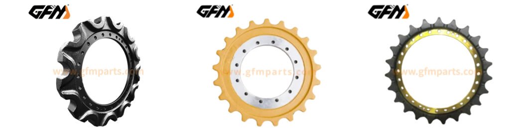
Estruturalmente, o sistema consiste em três partes principais:
- Roda motriz: conectada à saída da transmissão final, responsável pela entrada de energia.
- Roda dentada: encaixa-se precisamente nos elos da esteira para transmitir potência e controlar o movimento.
- Corrente de esteira: transporta e converte movimento rotacional em propulsão terrestre.
Na prática, o sistema não funciona sob condições ideais de carga uniforme. Em vez disso, ele experimenta continuamente uma combinação de carga de impacto, carga de atrito e distribuição desigual de carga. Por exemplo, ao operar em cascalho ou terreno irregular, a pressão de contato da superfície dos dentes pode aumentar instantaneamente, criando áreas localizadas de alta tensão.
Esse estado de tensão flutuante repetida significa que a roda motriz e a roda dentada não são apenas componentes de transmissão, mas também peças estruturais sujeitas a alta tensão.
Análise dos padrões de desgaste comuns e das causas de falhas
O desgaste das rodas motrizes e das engrenagens geralmente é um processo gradual, e a falha resulta da combinação de múltiplos fatores, e não de uma única causa.
1. Desgaste do perfil dentário
O desgaste do perfil do dente geralmente começa com um leve arredondamento da ponta do dente e gradualmente evolui para um afinamento ou deformação do formato do dente. Isso reduz a precisão do engrenamento com os elos da esteira e diminui a área de contato, aumentando a pressão localizada e acelerando o desgaste geral.
2. Desgaste irregular
O desgaste irregular geralmente aparece em um dos lados da superfície do dente e costuma ser causado por tensão desigual na pista ou por carga desequilibrada a longo prazo. Essa condição pode deslocar a linha central de engrenamento e reduzir a estabilidade operacional.
3. Quebra de dentes e falha por fissura
Esse tipo de falha é um problema de dano estrutural e geralmente ocorre em condições de trabalho de alto impacto, como escavação de rochas ou operações de giro de cargas pesadas.
As fissuras geralmente se iniciam na raiz do dente ou em áreas de concentração de tensão e se propagam gradualmente sob carga cíclica. Quando a fissura atinge um ponto crítico, leva à quebra parcial ou à perda do dente, e o componente torna-se irreparável.
4. Condições de operação e fatores de desalinhamento
Lama, areia e cascalho que entram na área de contato da engrenagem criam desgaste abrasivo contínuo. Além disso, pequenas discrepâncias entre os componentes também podem levar a desgaste anormal localizado e falha acelerada.
Como selecionar cientificamente rodas motrizes e engrenagens
A seleção de rodas motrizes e rodas dentadas não é simplesmente um processo de correspondência dimensional, mas uma decisão sistemática que envolve o desempenho do material, o processo de fabricação e a adaptação às condições de trabalho.
1. Seleção de Materiais
Os materiais comuns incluem aços-liga de alta resistência, como o 40MnB e o 35SiMn, que oferecem um bom equilíbrio entre resistência ao desgaste e resistência ao impacto. O importante não é a dureza máxima, mas sim o equilíbrio entre dureza e tenacidade.
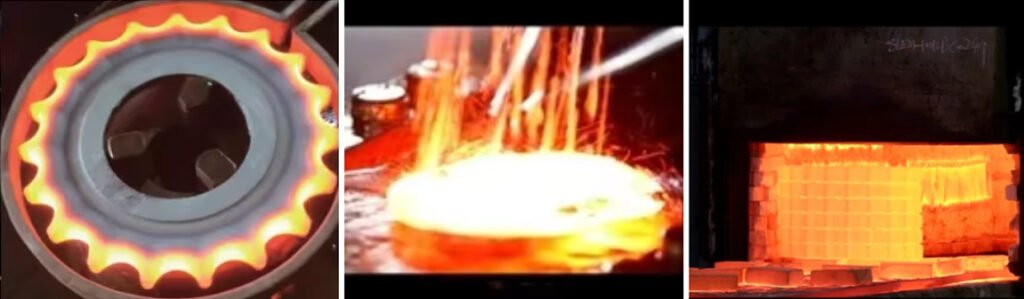
2. Processo de Tratamento Térmico
O tratamento térmico é um fator essencial para determinar a estabilidade do desempenho. Normalmente, utiliza-se uma combinação de têmpera total e endurecimento superficial para proporcionar alta dureza superficial, mantendo a tenacidade interna.
3. Precisão na usinagem do perfil do dente
As rodas motrizes e as rodas dentadas são componentes de engrenamento de precisão, e a consistência do passo dos dentes é fundamental. Erros excessivos de usinagem podem causar impacto no engrenamento, ruído e concentração de desgaste localizado. A usinagem CNC de alta precisão ajuda a garantir um engrenamento suave.
4. Princípios de adequação das condições de trabalho
Ambientes de trabalho diferentes exigem características de desempenho diferentes:
As condições de mineração enfatizam a resistência ao impacto; as condições de construção enfatizam a durabilidade geral; ambientes lamacentos exigem melhor desempenho de autolimpeza e anti-entupimento.
A correspondência adequada melhora a vida útil geral do sistema.
Etapas e precauções para a substituição da roda motriz e da roda dentada
A substituição das rodas motrizes e das rodas dentadas é uma operação padrão de manutenção do material rodante, mas requer o cumprimento rigoroso dos procedimentos.
1. Etapas de Substituição
- Preparação de segurançaDesligue a máquina, desconecte o sistema de energia, libere a pressão hidráulica e trave a esteira para evitar movimentos.
- Liberação da tensão da esteiraLibere lentamente a graxa de tensionamento para soltar a esteira e evitar o recuo durante a desmontagem.
- Remoção de componentes antigosUtilize ferramentas profissionais para remover os parafusos e desencaixe cuidadosamente a roda motriz ou a roda dentada antiga sem danificar o sistema de transmissão final.
- Instalação de novos componentesAo instalar o roda dentada de transmissão da escavadeiraCertifique-se de que o perfil do dente esteja totalmente alinhado com os elos da esteira. A instalação forçada é estritamente proibida.
- Ajuste de tensãoAjuste a tensão da esteira de acordo com as especificações do equipamento para garantir que esteja dentro da faixa de operação adequada.
- Inspeção de teste de funcionamentoLigue a máquina sem carga durante 10 a 15 minutos e observe o ruído, a vibração e as condições de engrenamento.
2. Precauções
- Sem instalação forçadaMartelar ou forçar a montagem pode causar danos estruturais ou concentração de tensão.
- Garantir o alinhamento preciso da malhaO alinhamento correto é essencial para prevenir o desgaste anormal precoce.
- Evite misturar peças novas com peças antigas.O desgaste irregular no sistema de esteiras acelerará o desgaste dos componentes novos.
- Controle a tensão adequadaA condição de tensão afeta diretamente a vida útil e a estabilidade operacional.
- Verificação completa da execução do testeA execução de testes é essencial para identificar problemas ocultos de instalação.
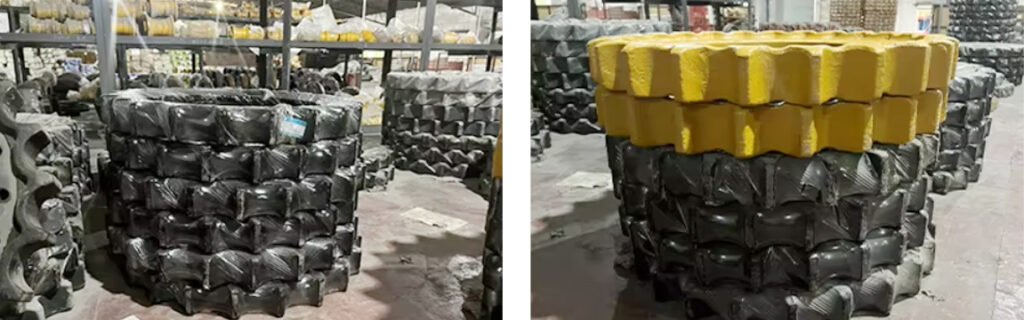
Por que escolher a GFM para a fabricação de rodas motrizes e rodas dentadas?
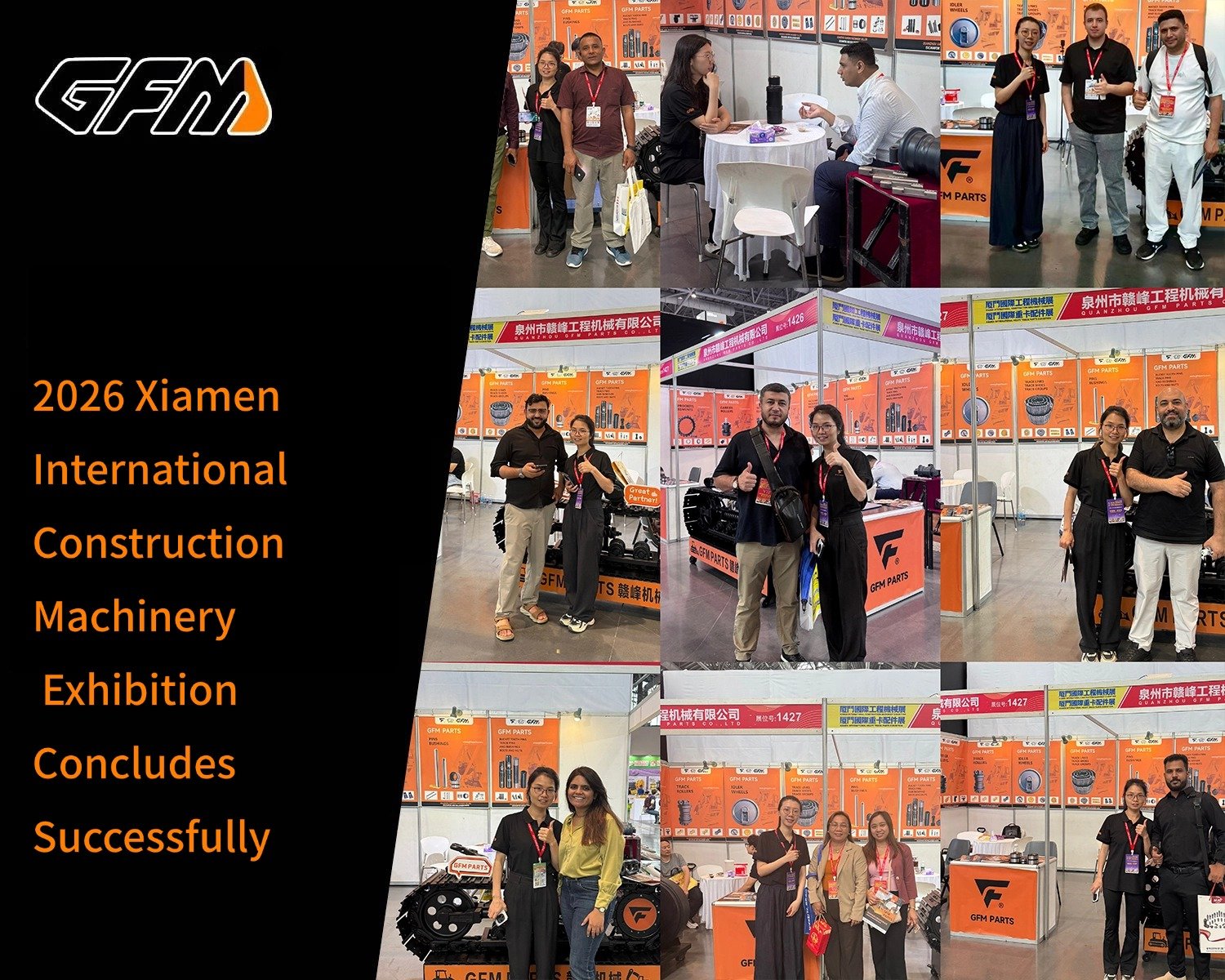
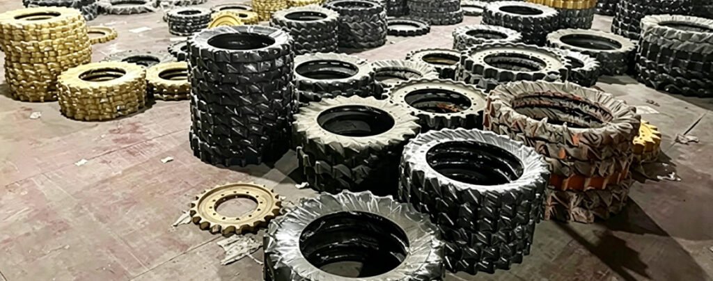
A GFM é uma fábrica especializada em componentes de material rodante para máquinas de construção, com mais de 15 anos de experiência em fabricação. Ela produz mais de 1.000 tipos de peças de material rodante e oferece produção em massa estável e capacidade de fornecimento global.
- Fabricação em larga escala e longa experiência: A GFM possui 15 anos de experiência na produção de peças para material rodante, abrangendo mais de 1.000 tipos de componentes, incluindo rodas motrizes e rodas dentadas, garantindo uma capacidade de fornecimento estável a longo prazo.
- Sistema padronizado de garantia da qualidade: Todos os produtos são fornecidos com um período de garantia de pelo menos 1 ano ou 2.000 horas de funcionamento, garantindo resistência ao desgaste e confiabilidade estáveis em condições normais de trabalho, reduzindo efetivamente os custos de manutenção e os riscos de tempo de inatividade.
- Fornecimento direto da fábrica e vantagem de custo: A GFM opera sob um modelo de venda direta da fábrica com um sistema de preços de fábrica 100%, eliminando intermediários e oferecendo forte competitividade de preços em comparação com produtos similares.
- Compatibilidade com as principais marcas de equipamentos: Os produtos são compatíveis com as principais marcas de máquinas de construção, como Komatsu, Hitachi, Caterpillar, Volvo, Kobelco, Doosan, Hyundai, Kubota, Bobcat, Yanmar, Sany, Liugong, XCMG e Shantui.
| Obtenha um orçamento rápido e gratuito | E-mail: henry@gfmparts.com | Whatsapp: +86 17705953659 |
Embora as rodas motrizes e as rodas dentadas sejam componentes relativamente pequenos, são peças críticas de transmissão de potência no sistema de material rodante da escavadeira, afetando diretamente a eficiência da máquina e o custo de manutenção.
Ao compreender seus princípios de funcionamento, mecanismos de desgaste, critérios de seleção e procedimentos adequados de substituição, a vida útil pode ser efetivamente prolongada e o tempo de inatividade não planejado pode ser reduzido.
Quando os usuários compreendem claramente o mecanismo de funcionamento da roda dentada de acionamento da escavadeira e adotam um sistema de fornecimento de fabricação estável, como um fornecedor confiável, fornecedor de rodas dentadas para escavadeiraEssencialmente, estão construindo um sistema de operação de material rodante mais confiável e econômico, alcançando eficiência a longo prazo e benefícios econômicos.