
Table of contents
- Overview of the bulldozer undercarriage system
- Common fault types and causes
- Diagnosis and repair methods for chain wear and breakage
- Tips for fault detection and repair of sprocket and idler
- Prevention and replacement steps for drive gear and sprocket damage
- Troubleshooting and adjustment guide for tensioning devices
- Practical suggestions for chassis maintenance and care
The bulldozer undercarriage is the most critical load-bearing and traveling system of the whole machine, bearing huge loads and complex working conditions. Once the chassis fails, it will not only cause the whole machine to stop, but also bring high maintenance costs and construction delays. Therefore, it is crucial for equipment managers and maintenance technicians to have a deep understanding of the common failure types of various chassis components and master systematic detection and maintenance methods.
Overview of the bulldozer undercarriage system
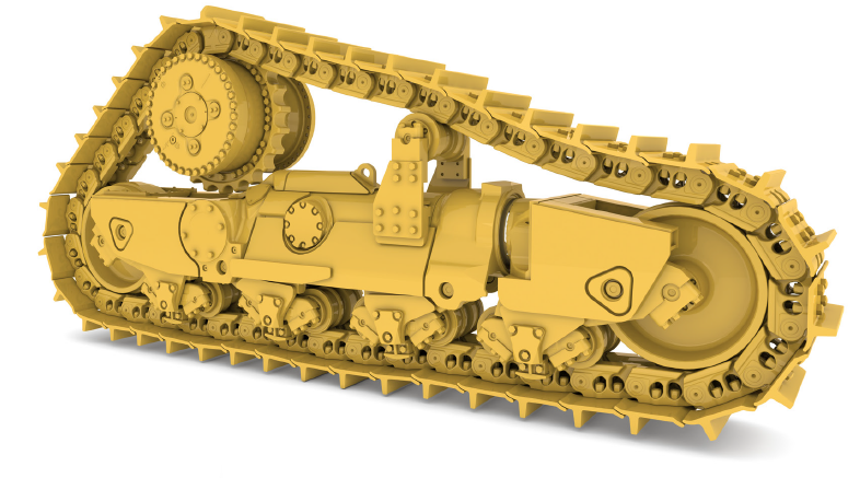
The bulldozer undercarriage system is mainly composed of track chain, carrier roller, Idler, drive sprocket, track tensioner and several load-bearing rollers.
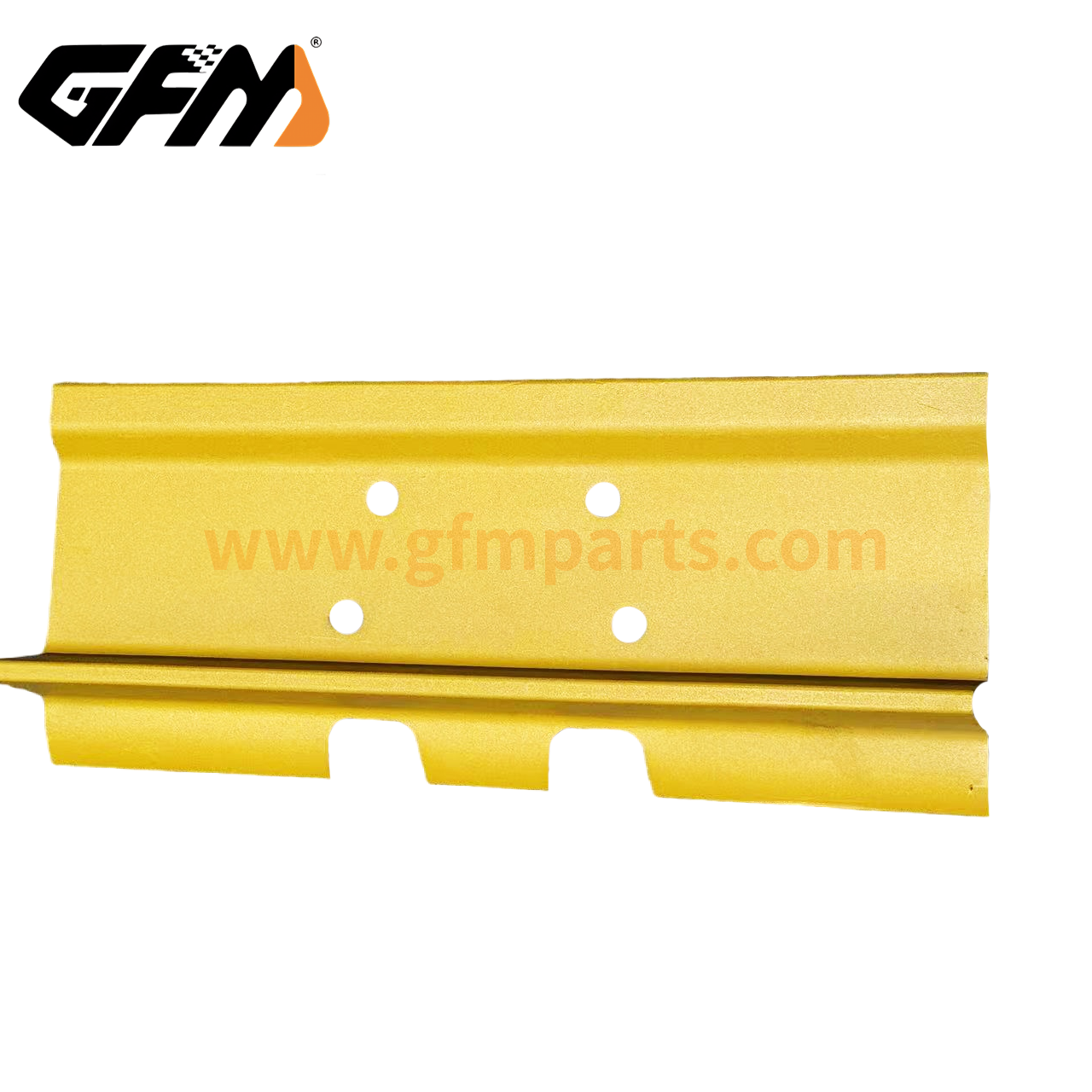
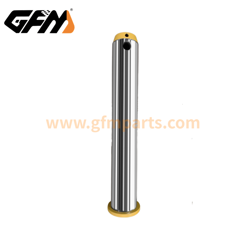
- Track chain: composed of chain plate, pin shaft and sleeve, it is the main structure connecting the left and right supporting wheels and bearing the weight of the whole machine.
- Carrier roller: located at the bottom of the chassis, used to support the machine body and guide the operation of the track chain.
- Guide wheel: installed at the front end, responsible for maintaining the tension state of the track chain and guiding the return chain.
- Drive gear: driven by a hydraulic motor, meshing with the rail chain to make the machine move forward or backward.
- Tensioning device: adjust the tension of the rail chain through a hydraulic cylinder or mechanical screw to avoid derailment or too loose phenomenon.
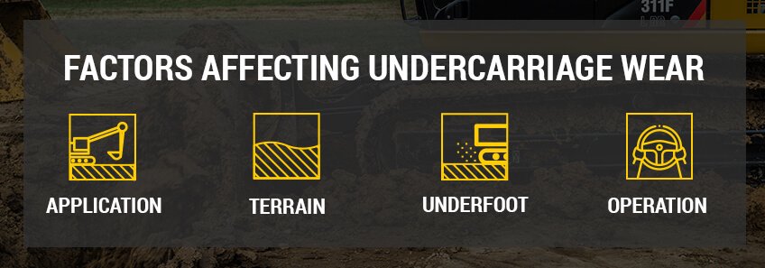
The cost of the chassis system accounts for about 20% of the purchase price of the whole machine, but its maintenance cost is as high as more than 50% of the cost of parts and services of the whole machine (average 50%), which is the most concentrated part of the maintenance expenditure of heavy equipment, directly affecting the life cycle cost and unit operating cost of the whole machine. In addition, different working environments (such as stone yards, muddy sites, frozen soil, etc.) will accelerate the wear and damage rate of chassis components and shorten the service life. Therefore, correctly understanding the structure of the chassis system and carrying out targeted maintenance in combination with the characteristics of the working conditions is the basis for achieving efficient operation and maintenance management.
Common fault types and causes
According to on-site maintenance statistics, bulldozer chassis faults can be mainly classified into the following categories:
- Wear: The clearance of the pin sleeve is too large and the surface of the chain plate is worn thin.
- Fracture: The rail chain pin shaft is broken and the chain plate is broken.
- Derailment: Insufficient tension or failure of the guide wheel causes the chain to fall off.
- Looseness: Failure of the tensioning device or hydraulic leakage causes the track chain to be too loose.
- Jamming: The sprocket or guide wheel bearing is damaged and cannot rotate freely.
These faults are mainly caused by the following reasons:
- Improper operation: Sharp turns and overloading of side slope operations will cause a sudden increase in lateral force and accelerate component damage.
- Maintenance omissions: Insufficient or improper use of lubricating grease, and aging of seals that are not replaced in time.
- Mixed use of parts: The quality of non-original accessories is uneven, and the matching accuracy is poor after installation.
- Environmental factors: Foreign objects such as mud, sand, and stones invade, aggravating component wear and impact.
Only after understanding these causes can targeted prevention and maintenance measures be implemented in subsequent chapters to reduce the recurrence of faults.
Diagnosis and repair methods for chain wear and breakage
Fault symptom identification
Increased gap between chain links: At the end of normal service life, when the wear of the pin sleeve causes the lateral gap between the chain links to exceed the manufacturer’s recommended value (usually > 0.5 mm), it can be determined that replacement is required.
Abnormal noise and vibration: “clicking” or “squeaking” sounds occur during operation, accompanied by slight vibration of the machine body, mostly due to local damage to the chain.
Detection methods
Ruler measurement: Use a vernier caliper to measure the distance between chain links and the inner diameter of the pin sleeve to determine the degree of wear.
Ultrasonic thickness measurement: Ultrasonic thickness detection of the chain plate is performed to quantify the wear thickness difference.
Visual inspection: After disassembly, check whether there are cracks or fatigue marks on the surface of the chain plate and pin shaft.
Repair steps
Disassembly preparation
- Stop the machine and carry out on a flat ground to ensure the stability of the machine body.
- Use a suitable jack to support the machine body to prevent accidental sinking.
Chain disassembly
- First loosen the tensioning device and remove the guide wheel.
- Use the chain separator (Master Link Tool) to remove the chain link.
Replace the chain link and pin bushing
- Select the pin bushing and chain link assembly that are consistent with the original factory specifications.
- Apply an appropriate amount of anti-wear grease before installation, and ensure that the fit clearance meets the manual requirements (usually 0.1-0.3 mm).
Adjust the tension
- Use the chain tension tester to measure, and the tension is generally recommended to be set between 30-50 kN. Please refer to the vehicle manual for details.
- After tensioning, roll and press several strokes forward and backward, re-measure the gap and fine-tune.
Through the above methods, the rail chain failure rate can be controlled within an acceptable range.
Tips for fault detection and repair of sprocket and idler
Common problems
Bearing wear or edge collapse: causes the sprocket wheel to rotate unsmoothly and heat up quickly.
Roller jam: Mud or hard objects are embedded, causing the roller to be unable to rotate freely.
Detection method
Infrared thermal imaging detection: The thermal imager scans the roller temperature distribution, and the high temperature point often corresponds to the bearing failure.
Manual rotation test: After removing the dirt, rotate the roller vigorously to feel whether there is any wear or grit.
Disassembly and replacement process
Hydraulic puller disassembly: Apply uniform tension between the roller and the bushing to avoid eccentric force damage.
Bearing replacement: Select double-lip rubber sealed bearings with excellent sealing performance and regularly maintain with grease.
Installation correction: Be sure to ensure the concentricity of the roller, and the error must not exceed 0.1 mm, otherwise it will accelerate wear.
Lubrication and sealing
High-performance lithium-based grease: It has good water erosion resistance and is recommended to be lubricated every 200 working hours or every week.
Rubber sealing ring: Check the aging condition regularly, and it is recommended to replace it every 1000 working hours.
Refining these steps can significantly extend the service life of the sprocket and guide wheel.
Prevention and replacement steps for drive gear and sprocket damage
Damage manifestations
- Tooth surface depression and groove: Common when foreign objects are caught or lubrication is poor.
- Tooth deformation: Poor meshing due to excessive impact load or eccentric wear.
Preventive measures
- Clean up the mud and sand regularly: Use a high-pressure air gun or water gun, and install a screen at the rear end to intercept large foreign objects if necessary.
- Uniform force operation: Avoid single-sided side slopes or sudden stops, and try to keep walking in a straight line.
Replacement process
- Unlock the locking bolts: Loosen first and then remove, to avoid removing all bolts at once and causing the gear to fall.
- Use professional gear pullers: Ensure straight pull-out, and do not use a crowbar to pry hard.
- Installation correction:
- Check the concentricity to ensure that the deviation between the drive shaft and the sprocket center is less than 0.05 mm.
- Use a pitch gauge to check that the tooth spacing meets the specifications.
Strictly follow the above process to minimize the failure rate of the drive system.
Troubleshooting and adjustment guide for tensioning devices
Common faults
Cylinder leakage: Failure of the sealing ring or damage to the pipeline causes a decrease in tension.
Screw jam: The mechanical tensioner cannot rotate due to rust or impurities.
Detection method
Pressure gauge measurement: Connect a pressure gauge to the connection point of the hydraulic tensioning device to detect whether the working pressure of the cylinder meets the standard (generally 15-25 MPa).
Seal detection fluid: Apply soapy water to the suspected leak and observe the location of the bubble.
Adjustment steps
Loosen first and then tighten: First loosen the tensioning mechanism completely, then slowly pressurize to the recommended preload to avoid “sudden tightening” causing chain wear.
Step-by-step test: After adjusting the tensioning screw by 1 cm, drive a short distance of 100 m, re-test the chain tension and make fine adjustments.
Daily maintenance
Keep the cylinder and pipeline clean to prevent mud and sand from entering.
Replace seals regularly, it is recommended to replace them every 2000 working hours or two years.
Practical suggestions for chassis maintenance and care
Inspection cycle and process
| Cycle | Inspection content | Tools |
| Daily | Clean foreign objects and check chain tension | High-pressure air gun, tensioner |
| Weekly | Lubricate sprocket, guide wheel, and docking bolts | Lithium-based grease, torque wrench |
| Monthly | Check the wear thickness of rail chain and roller, and the sealing condition of oil cylinder | Vernier caliper, ultrasonic thickness gauge, pressure gauge |
Working environment optimization
Use protective net: Install stone retaining net at the front to reduce the impact of stones on the chassis.
Regularly sprinkle water to reduce dust: Soften dry soil to prevent high dust environment from aggravating friction.
Operation specification
Slow start: Avoid chain tearing caused by rapid acceleration without load.
Rapid turn deceleration: Slow down and increase chain tension before turning.
Avoid idling: Long-term idling in place will cause excessive wear on the drive gear and chain.
| Hızlı ve ücretsiz bir teklif alın | E-posta: henry@gfmparts.com | Whatsapp: +86 17705953659 |
Dozer undercarriage parts maintenance is a systematic project that requires coordinated efforts from structural cognition, fault diagnosis, professional tool application to daily maintenance. Through scientific inspection processes, precise testing methods, standardized maintenance procedures, and data-based management methods, the chassis failure rate can be effectively reduced and the operational reliability and production efficiency of the entire machine can be improved to a new level.