Table of contents
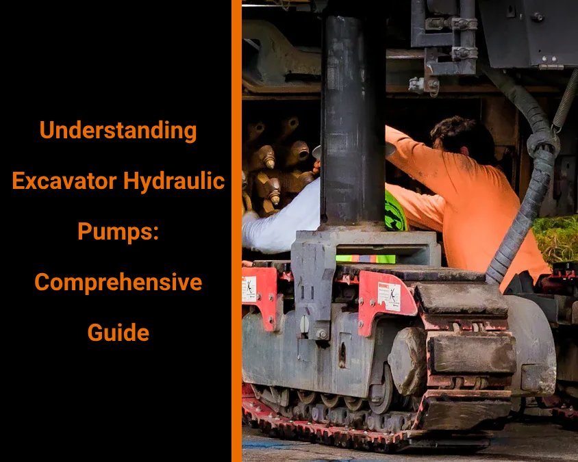
At the construction site, when an excavator swings its bucket to dig earth or easily flattens the ground, we often only see its huge figure and roaring engine, but rarely pay attention to its “heart” – the hydraulic pump. It is this invisible device that converts the engine’s mechanical energy into high-pressure oil flow, driving the boom, dipper, slewing mechanism and travel motor in a precise and controllable manner. It can be said that the health and efficiency of the excavator hydraulic pump directly determine the production efficiency, safety and operating costs of the excavator.
As an excavator parts manufacturer, GFM has combined the bench test data of thousands of pump groups and numerous field application cases to deeply summarize the “practical guide” for hydraulic pump selection, fault diagnosis and maintenance. This article will provide you with a comprehensive and practical reference manual from the core components of the pump body, the principle of collaborative work, the causes of common faults to the details of maintenance. Whether you are an excavator maintenance veteran or a novice in the field of hydraulics, you can find operational and practical experience and skills here to make the excavator run stably and efficiently and extend its service life.
Key components of hydraulic pump accessories for excavators
To understand the performance and failure of hydraulic pumps, we must start with its “parts list”. The following seven core components are indispensable.
Housing
The pump body is the “skeleton” of the entire hydraulic pump, usually made of high-strength cast steel or aluminum alloy with precision machining. Its inner cavity not only carries high-pressure moving parts such as rotors and plungers, but also withstands pressure pulsation shocks of hundreds to thousands of times per minute.
- Structural features: The inner wall of the pump body must ensure micron-level machining accuracy, and the tolerance must be controlled within the range of 0.01-0.02 mm to ensure the oil channel seal and component alignment.
- Material selection points: High-quality pump bodies are mostly made of ductile iron or aviation-grade aluminum alloy with good fatigue and corrosion resistance, and heat treatment processes are used to improve hardness and wear resistance.
- Inspection method: Use a three-coordinate measuring machine (CMM) to detect the geometric dimensions of the inner hole and oil channel; and perform a pressure test to confirm that there is no leakage and plastic deformation.
Pistons
The plungers are the “main force” of hydraulic pumps for oil suction and oil pressure. They are usually arranged in the rotor sleeve with 6-10 equal intervals. They reciprocate along the sliding surface of the swash plate to realize the in and out of the oil.
- Material and processing: 45# steel or alloy steel is commonly used after carburizing and polishing, and the surface hardness can reach HRC58-62, ensuring wear resistance and sealing.
- Function principle: When the angle of the swash plate changes, the plunger will produce axial displacement, forming a volume change; thus, negative pressure oil suction is generated, and then the oil is pushed to the outlet.
- Common faults: Wear or scratches on the plunger will cause volume leakage and the pump efficiency will drop sharply. The surface finish needs to be checked regularly and the wear marks should be observed with a metallographic microscope.
Valve Plate
The valve plate is the “distribution center” inside the plunger pump. Precision holes are opened on its plane to control the inlet and outlet switching of the hydraulic oil.
- Design points: The aperture is strictly matched with the number and phase of the plunger, and the reversing structure determines the size of the pressure pulsation and the noise level.
- Material and manufacturing: Commonly used high-wear-resistant alloy steel, after deep treatment of nitriding or carburizing, the surface hardness can reach HV900 or above.
- Inspection method: Use a laser thickness gauge to check the opening size and flatness to ensure a runout of ≤0.01 mm. And use the filter paper method to check the sealing.
Swash Plate
The swash plate converts the axial rotational force into the reciprocating linear motion of the plunger by rotating with the shaft. The swash plate angle determines the displacement of the pump.
- Structural features: The inclination angle is generally adjustable from 0° to 25°. The larger the inclination angle, the higher the displacement; modern models are mostly equipped with an electronically controlled inclination angle adjuster to achieve stepless adjustment.
- Surface treatment: Chrome plating or nitriding treatment is required, with low surface friction coefficient and good wear resistance to ensure long-term sliding without heat generation.
- Detection method: Use a three-coordinate and angle measuring instrument to confirm the inclination, and use a surface profiler to detect the roughness.
Bearings & Seals
The bearing is responsible for keeping the pump shaft and the pump body concentric, and the shaft seal prevents the high-pressure oil from leaking outward. Both ensure that the pump unit can operate stably and long-term under high-pressure conditions.
- Bearing selection: Needle roller or tapered roller bearings are usually used to withstand radial and axial bidirectional loads. Apply high-performance grease, and the replacement interval can reach 2,000 hours.
- Seal material: Fluorine rubber, polytetrafluoroethylene (PTFE) and high-temperature resistant polyurethane oil seals, which are resistant to aging, high temperature and oil.
- Daily inspection: Check the bearing clearance and noise every 300 hours, replace the seal ring regularly and check the dust cover to avoid particle intrusion.
Inlet & Outlet Valves
Some high-end pump units add independent valve plate mechanisms before and after the oil distribution plate to further smooth pressure pulsation and improve anti-cavitation ability.
- Structural principle: The oil suction valve is equipped with a one-way valve at the oil inlet to prevent backflow and oil discharge; the oil discharge valve outputs after stabilizing the pressure, and some designs also have an oil cooling circuit.
- Material and processing: The valve disc is mostly made of high-chromium cast steel, and the valve seat mating surface needs to be polished to below Ra0.2 to ensure switching sensitivity.
- Maintenance points: Regularly disassemble and inspect the valve disc and valve seat clearance ≤0.02 mm to prevent sticking or oil leakage.
Relief Valve
When the system pressure exceeds the set value, the overload valve will automatically open and return the excess oil to the oil tank to protect the pipeline and pump body from impact.
- Setting principle: The spring preload determines the valve opening pressure, which is generally set at 90%-95% of the maximum rated pressure of the pump.
- Inspection and calibration: A manual pressure pump and a digital pressure gauge are required for calibration, and re-inspection is performed every six months or 1,000 hours to ensure that the valve opening pressure deviation is ≤±3%.
- Common faults: Spring fatigue or valve core jamming can cause inaccurate valve opening or pulsating pressure relief.
How the hydraulic pump components of excavators work together
After understanding the various components, let’s take a look at the “tacit cooperation” of the hydraulic pump during operation – a complete working cycle can be divided into four stages: oil suction, pressurization, delivery, and pressure relief.
Oil suction stage: forming negative pressure – breathing moment
When the engine drives the pump shaft to start rotating, the plunger on the swash plate is pulled away from the oil distribution plate, and the internal volume of the cavity where the plunger is located increases rapidly, generating negative pressure. At this time, the oil suction valve opens and hydraulic oil that meets the viscosity specification is sucked from the oil tank. Good oil suction patency can avoid air entrainment, otherwise, once cavitation occurs, fine cracks on the metal surface will occur, shortening the life of the pump unit.
- Practical tips: When cold starting, let the pump run idle for a few seconds to ensure that the oil circuit is fully filled with oil to avoid cavitation.
Pressurization stage: from volume reduction to high-pressure output
As the swash plate continues to rotate, the inclination angle enters the positive area, the plunger is pushed into the cylinder by the swash plate, the cavity volume decreases, and the oil pressure rises rapidly. Ideally, the system pressure is kept constant between the specified values to meet the power output requirements.
- Professional tools: Digital pressure tester can record the pressure curve in real time. During debugging, ensure that the pressure rise rate is smooth and there is no obvious jitter.
Delivery stage: High-pressure oil circuit – refueling the actuator
The pressurized oil enters the main oil circuit through the drain valve and is transported to the boom cylinder, stick cylinder, swing motor and travel motor along the high-quality high-pressure oil pipe. Accumulators and buffers are usually installed in parallel in the system to balance impact and energy storage for smooth operation.
- On-site operation suggestions: Regularly check the bending radius of the hose to avoid it being lower than the manufacturer’s recommended value to prevent degumming or stratification of the inner layer.
Pressure relief protection: “life-saving operation” of the overload valve
When the actuator is suddenly blocked or the pipeline resistance is too large, causing the system pressure to exceed the preset value, the overload valve opens instantly to return the excess oil to the tank to keep the system pressure within a safe range. This “overflow protection” mechanism is the last line of defense for the safe operation of the hydraulic system.
- Maintenance tips: Use a high-precision pressure gauge and data acquisition module to record the frequency of overload valve operation. If it is frequently opened, check the pipeline resistance and filter blockage immediately.
Common problems with hydraulic pump parts for excavators
Even if you strictly follow the maintenance specifications, it is still difficult to avoid various faults. Here are the five most common problems on site, and how you can quickly locate and deal with them.
Leakage and pressure drop – “silent” efficiency killers
- Fault manifestations: heavy operating handles, insufficient power output, and system pressure cannot stably reach the rated value.
- Common causes:
- Shaft seal aging and micro cracks.
- O-ring deformation and hardening.
- The gap between the oil distribution plate and the pump body exceeds the standard.
- The high-pressure oil pipe joint is loose.
- Diagnostic steps:
- Clean the pump body and pipelines, apply a thin layer of dye penetrant, and run without load for 3 minutes.
- Check the position of the penetrant after shutdown to determine the leak point.
- Remove the corresponding seals, measure the gap or replace new seals.
- Preventive measures: Use fluororubber seals with excellent high temperature resistance and oil aging resistance, and the regular replacement cycle should not exceed 1,000 hours.
Abnormal noise and vibration – the hidden worries behind “crackling” and “squeaking”
- Fault manifestation: obvious metal friction sound or low-frequency whistling during operation, abnormal vibration of the machine body.
- Common causes:
- Too much gas content in the oil, leading to cavitation.
- Scratches or pits appear on the surface of the plunger or oil distribution plate.
- The valve hole or valve disc is stuck.
- Diagnostic method:
- Check the oil suction filter element and the oil level of the oil tank to confirm that there are no bubbles in the oil suction pipeline.
- Disassemble the oil distribution plate and use the white paper method to detect the scratch position.
- Measure the matching clearance between the valve hole and the valve disc, and clean it with an ultrasonic cleaner if necessary.
- Prevention tips: Keep the oil cleanliness below ISO 18/16/13 level and avoid water content exceeding 500 ppm.
Unstable or jumping displacement – “dramatic” operation experience
- Fault manifestation: The same operating lever moves, the excavator execution speed is fast and slow, and the pressure gauge pointer fluctuates greatly.
- Cause analysis:
- Insufficient lubrication of the swash plate causes the sliding surface to stick.
- The fatigue force of the plunger spring decreases and the return is not timely.
- The clearance between the oil distribution plate and the oil distribution hole increases.
- Troubleshooting process:
- Remove the swash plate assembly and check the oil channel and grease condition.
- Test the spring force value. If it is 20% lower than the nominal value, it needs to be replaced.
- Use a feeler gauge to measure the clearance and polish it.
- Optimization suggestion: A thin layer of lubrication should be applied to the swash plate sliding surface and the plunger end face every time the oil is changed to avoid dry friction.
Overheating phenomenon – the hidden danger of “high temperature dryness”
- Fault manifestation: The oil temperature quickly exceeds 80℃, and the excavator continues to work for 15 minutes before the output decreases.
- Cause analysis:
- The viscosity of the hydraulic oil is high or it is not preheated when starting at low temperature in winter.
- The oil cooler (radiator) is blocked by mud or dust.
- Axial or radial leakage in the system aggravates internal friction and heating.
- Troubleshooting and solutions:
- Use a handheld infrared temperature gun to measure the temperature difference between the inlet and outlet of the oil port. If it is >15℃, it means that the radiator is blocked.
- Check whether the oil temperature sensor reading is accurate and ensure that the display is correct.
- Adjust the preheating process according to the ambient temperature. When the environment is below 5℃, preheat for 3-5 minutes without load.
- Daily maintenance: Remove the radiator every 500 hours, clean it with a high-pressure water gun, and check whether the heat sink is deformed.
Frequent overload pressure relief action – the role pressure of “safety valve”
- Performance phenomenon: Frequent overflow when the system pressure reaches the set value, and the action is obviously stuck.
- Root cause:
- Increased oil circuit resistance (too many elbows, blockage).
- The primary filter or precision filter element is blocked.
- The overload valve spring preload is unbalanced or the valve core is stuck.
- Detection and treatment:
- Disconnect the branch pipeline and check the pressure drop section by section.
- Replace or backwash the filter element to keep the impurity content below 5 microns.
- Disassemble and inspect the overload valve, calibrate the spring and replace the worn parts.
- Preventive principle: Try to reduce 90° sharp bends when designing, and keep the minimum curvature radius of the pipeline ≥5×pipe diameter.

Maintenance skills for hydraulic pump parts of excavators
“Sharpening the knife does not delay the chopping of wood”, timely and scientific maintenance is the key to extending the life of the hydraulic pump and ensuring construction efficiency. Please be sure to include the following six major maintenance measures in your schedule.
Daily inspection: observation, hearing, and hand exploration
- Visual inspection: Before each shift, clean the pump body and surrounding pipes. Observe for exposed oil stains, loose bolts or abnormal cracks. Any small oil leakage may be a “precursor” to a major failure in the future.
- Listening judgment: Start the machine without load, put your ear close to the pump body, and listen to the movement sound. It should be smooth and without intermittent metal friction sound; once “clucking” or “whistling” occurs, stop the machine immediately for diagnosis.
- Touch monitoring: Touch the surface of the pump body lightly, and the temperature should be controlled between 40℃–70℃ (measured at 25℃ without load). Too high or too low temperature may affect the life of the seal and the performance of the oil.
Filter and oil management: keep the oil “clean” all the time
- Filter replacement: It is recommended to replace the main filter every 250-500 hours under normal working conditions; in dusty or humid working conditions, it should not exceed 250 hours. Do not exceed 500 hours to avoid clogging of the filter element, resulting in system vacuum or insufficient pressure.
- Precision filtration: Equipped with 5μm precision filter element to protect high-precision components such as pump units and proportional valves; the replacement cycle can be synchronized with the main filter element.
- Oil replacement: Generally, the hydraulic oil is fully replaced every 1,000-2,000 hours or annual overhaul. It is recommended to use medium-to-high viscosity hydraulic oil that meets ISO 11158 standards and has anti-wear (AW) and anti-oxidation (R&O) additives.
- Oil sample monitoring: Take oil samples every 500 hours and send them to a third-party laboratory for particle size (ISO 4406) and corrosiveness and moisture testing to ensure that the moisture is <500 ppm and the particle size is ≤18/16/13.
Bolt torque verification: tighten every “life bolt”
- Tool preparation: Use a digital torque wrench to pre-tighten in sections to prevent stress concentration on the pump body.
- Key points:
- The pump body cover bolts are usually required to be tightened to 35-40 N·m
- The valve plate cover bolts are 35 N·m
- The inclined plate adjustment spring cover is 40-45 N·m.
- Re-inspection frequency:
- The new pump should be re-inspected once in the first 50 hours after installation, and then every 300 hours
- It can be shortened to 200 hours under severe vibration or high load conditions.
Cleaning and lubrication: “drink full of oil” for parts
- Cleaning steps:
- When removing the seal and oil distribution plate, first wipe the seal groove and oil distribution plate with low residual industrial alcohol (IPA)
- Then blow it clean with compressed air to avoid residual particles.
- Lubrication points:
- A layer of special extreme pressure grease should be applied to the inclined plate and the end face of the plunger
- A small amount of high temperature resistant lubricant can be applied to the gap between the bearing seat and the valve plate to ensure the sensitive action of the switch valve.
- Note: Avoid using silicone grease or ordinary engine oil, which will reduce the performance of the seal and bring chemical compatibility risks.
Vibration and temperature monitoring: real-time “physical examination”
- Vibration analysis:
- Equipped with a handheld vibration analyzer, a 38-point vibration scan is performed every 500 hours to record the amplitude and spectrum of the bearing, inclined plate and oil distribution plate area
- When the amplitude is abnormal or the characteristic frequency peak appears, it needs to be disassembled for inspection.
- Temperature monitoring:
- Install a surface-mounted temperature sensor to monitor the temperature of the pump upper shell and the oil return port of the oil tank
- When the oil temperature or pump body temperature exceeds 80℃, it will automatically alarm and limit the current or shut down.
On-site emergency response: from “rush repair” to “quick replacement”
- Quick repair tool kit:
- The emergency kit contains O-rings, flat washers, sealing strips, springs, bolt kits and simple disassembly and assembly tools
- Small seals can be quickly replaced on site to save downtime.
- Quick-change assembly: It is recommended that the construction site always have a set of GFM original pump assembly quick-change components. The disassembly and assembly and pipeline reflux operations can be completed within about 2 hours to restore basic power output.
- Emergency specifications:
- Before stopping, cut off the oil and power, relieve pressure and drain the oil
- After the quick change is completed, run at low speed for 5 minutes without load, check for leakage, and then gradually increase the load.

FAQ
Q1: How often should the hydraulic pump assembly be overhauled or replaced under normal working conditions?
Professional advice: GFM has confirmed through bench life testing that the pump unit can run stably for 10,000 hours under normal working conditions. It is recommended to start a comprehensive inspection 1,000 hours before reaching this mileage, including oil distribution plate clearance, plunger wear, bearing condition and seal aging. Under severe working conditions (high dust, high temperature, high humidity), the inspection can be advanced to 7,000-8,000 hours.
Q2: The pump unit has a “whistling” sound. How to quickly distinguish cavitation from mechanical wear?
Judgment points: Cavitation sounds like “grunting” or “clucking”, which often occurs when starting at low temperature or when the filter element is clogged. The noise generated by mechanical wear is sharper and has a metallic friction feel.
Troubleshooting process:
- Check the oil tank level and filter element in the cold state.
- Replace a section of the oil suction hose or clean the filter element. If the noise disappears, it is cavitation.
- If the problem persists, disassemble and inspect the oil distribution plate and plunger to observe the surface scratches or pits.
Q3: Can I replace the seal or plunger on site? What tools do I need to prepare?
Feasibility: Absolutely, but it must be done in a clean environment to prevent secondary contamination of particles.
Required tools:
Digital torque wrench (range 10–100 N·m)
O-ring remover, flat gasket and sealant spare parts package
Industrial alcohol, cleaning cloth and compressed air tank
Chinese/English version of pump body decomposition diagram and assembly manual
Operation points:
Be sure to relieve pressure and drain the oil before stopping
Tighten the bolts in a “cross” order when disassembling
Use dye penetrant to confirm that there are no leaks after assembly.
Q4: How to choose the most suitable hydraulic oil for the hydraulic pump?
Selection principle:
Meet ISO 11158 specifications, viscosity grade VG46–VG68.
Contains anti-wear (AW), anti-oxidation (R&O), and anti-corrosion additives.
Moisture content <500 ppm, acid value ≤0.5 mg KOH/g.
Seasonal adjustment:
When the environment is below 0℃ in winter, low-temperature flow improver or VG32 can be added to ensure smooth cold start.
When it is above 40℃ in summer, ensure sufficient heat dissipation and good temperature control.
Q5: Can hydraulic pumps and travel motors be interchangeable?
Professional answer: Strongly not recommended. Although the external dimensions are similar, there are essential differences between pumps and motors in valve port design, oil distribution plate displacement, and inner cavity clearance. Interchangeability will lead to seal failure, a sharp drop in efficiency, and even overheating and damage to the pump body.
| Get a quick free quote | Email: henry@gfmparts.com | Whatsapp: +86 17705953659 |
The above detailed content covers every aspect of excavator hydraulic pumps from component recognition, working principle, fault diagnosis to maintenance and emergency repair. I hope this guide will help you to deal with pump group problems at the construction site, and also help you to formulate a scientific maintenance plan to extend equipment life, reduce costs, and improve efficiency. Next time when the bucket digs up the earth, you can confidently tell yourself: every bit of the excavator’s power comes from your careful care of the hydraulic pump!